Configuration Tool
See Related Terms and Questions at the end of this section for more details on device configuration settings.
Devices Tab
Note: This tab is only available with the Basic and Full models of KioWare.
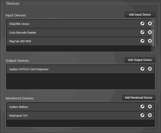
Devices That You Can Use
You can use both input and output devices with KioWare, as well as monitored devices. Input devices (e.g., barcode reader) receive data from a URL (web page), and output devices give out an item such as cash or digital cards. Output devices are set up in a similar way as input devices. Generally, you need to have custom JavaScript programming in your web pages for output devices to work correctly. (See Browser Tab, Related Terms and Questions for more details on JavaScript. For JavaScript commands that can be used with KioWare, see Scripting.)
For a list of specific devices that can be used with KioWare, visit the Devices page of the KioWare website.
Input Devices
The settings below will show when any input device is selected in the “Device Type” dropdown. For specific screen images, see the subsections below.
- Add Input Device - Select this button to add a new input device. The Configure Device window shows these settings.
Note: If also using KioWare Server, the “Friendly Name” (see below) and status of all input devices will be included in heartbeat data that is sent to the server (see Kiosk Management, Reports Tab, Heartbeat Report in the KioWare Server User Guide).
- Device Type - Select the type of input device connected to your kiosk or computer. (See table below for a list of supported device types.)
- Friendly Name - Enter the name used by KioWare JavaScript functions to identify a device entry in the KioWare list.
- Device Name - (Only available when certain devices are selected under “Device Type” above) The name that KioWare uses (on the back end) to identify the physical device with the underlying device-specific application programming interfaces (APIs). Select a device name from this dropdown box, or select the “<Auto Detect Name>” option to allow KioWare to auto-detect the name.
- Description - Enter a description for the device being used.
- Other Settings - All other possible settings on this window are described in the individual sections below.
- Edit (pencil icon) - Select this icon to change an input device.
- Delete (“X” icon) - Select this icon to remove an input device.
| Supported Input Device Types* |
- Access IS-Passport Reader
- Cash Code CCNet Bill Acceptor
- ccTalk Bill Acceptor
- ccTalk Coin Acceptor
- ccTalk Coin Acceptor (with escrow)
- ChipDNA Device
- Code Barcode Reader
- Code Corp Command Driven Barcode Device
- Custom Serial Device
- Datacap Device
- Digital Logic RF Tag Device
- DigitalPersona Fingerprint Scanner
- Elatec TWN4 Id/Storage Tag Device
- E-Seek M500 Id Scanner
|
- FEIG OBID Id/Storage Tag Device
- FreedomPay EMV
- Generic Keyboard Wedge Device
- Glory Front Cycle Control Currency Recycler
- Identive RF Tag Device
- Innova GPIO Board
- MagTek Excella Check Reader
- MagTek HID MSR
- MagTek ImageSafe Check Reader
- MEI Banknote Recycler (BNR)
- MEI Bill Acceptor
- Numato General Purpose IO Board
- Omron HVC Device
- Opticon Barcode Reader
|
- OTI Reader
- Raw SCard Id/Storage Tag Device
- RF Ideas Proximity Card Reader
- ScanShell OCR Device
- Shift4 EMV
- Symbol SNAPI
- Tanvas Touch Display
- Tenerum EMV
- Twain Imaging Device
- Wattbox Power Controller
- WIA Imaging Device
- Xtreme Power UPS (J60)
|
- * For specific devices that fall under these device types, visit the Devices page of the KioWare website.
Bill/Cash Acceptors, I/O Boards, and Sensors
The screen looks like this (or similar to this) when the “Device Type” dropdown is set to “Cash Code CCNet Bill Acceptor”, “ccTalk Bill Acceptor”, “ccTalk Coin Acceptor”, “ccTalk Coin Acceptor (with escrow)”, “Innova GPIO Board”, or “MEI Bill Acceptor”.

- COM Port - This dropdown contains a list of all available communications (COM) ports on the system. For serial devices (non-USB), select the COM port assigned to the device, or you can enter a new one. If you do not know what COM port a device uses, use Windows Device Manager to find it.
- Open the Windows Control Panel. (In Tile view of Windows 8 and higher, place mouse at the extreme bottom left corner of the screen and, after the tooltip appears, right click to display the hidden context menu. Select “Control Panel” in this menu.)
- Select the “System” icon (“System and Security” icon in Windows 7 and higher).
- Select the “Hardware” tab (“Hardware and Sound” link in Windows 7 and higher).
- Select the “Device Manager” icon.
ChipDNA Devices
The screen looks like this when the “Device Type” dropdown is set to “ChipDNA Device”.
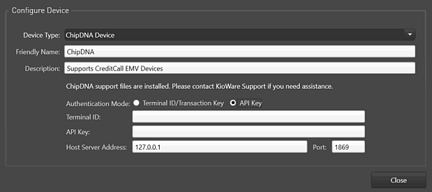
- Click Here to Download the Latest ChipDNA Files - Select this button to download the most up-to-date ChipDNA files that support use of these devices. Note: This button only shows when the latest ChipDNA files have NOT been downloaded. If files have been downloaded, a message indicates that the files are installed (see image above).
- Terminal ID - An ID that is unique to the user's CreditCall (payment processor for these devices) account and is generated/sent to a user when that user creates a CreditCall account.
- Authentication Mode - Select the type of authentication to be used when accessing CreditCall services (“Terminal ID/Transaction Key” or “API Key”).
- API Key - (Only available when “Authentication Mode” above is set to “API Key”) Enter the CreditCall API key (unique ID number that CreditCall gives to users who want to do custom programming using its application programming interface).
- Host Server Address - Set the IP address of the server that is hosting the CreditCall services.
- Port - Enter the port number for the server that is hosting the CreditCall service.
Custom Serial Device
The screen looks like this when the “Device Type” dropdown is set to “Custom Serial Device”.
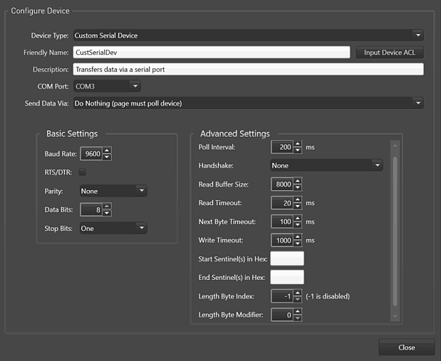
Note: Refer to your device's documentation to determine which serial settings should be changed (in most cases, only “Baud Rate” and “RTS/DTR” require updating). However, it is important to remember that every device is different, and settings such as “Length Byte Index” and “Start Sentinel(s)”/“End Sentinel(s)” may result in more efficient and reliable reads if the device's protocol allows for them to be used.
- COM Port - This dropdown contains a list of all available communications (COM) ports on the system. For serial devices (non-USB), select the COM port assigned to the device, or you can enter a new one. If you do not know what COM port a device uses, use Windows Device Manager to find it (see Bill/Cash Acceptors, I/O Boards, and Sensors, COM Port above for these steps).
- Send Data Via - Tells KioWare how users should be notified when input device data is ready to be retrieved (see Notifying Users About Input Device Data below).
Basic Settings
- Baud Rate - Maximum number of bits that the device is able to process per second (default is 9600).
- RTS/DTR - If checked, the RTS/DTR (Request To Send/Data Terminal Ready) functions will be used.
- Parity - Select the error detection method to be used.
- None - (Default) No parity bit is sent.
- Odd - The parity bit is set so that the number of “logical ones” must be odd.
- Even - The parity bit is set so that the number of “logical ones” must be even.
- Mark - The parity bit is always set to the mark signal condition (logical 1).
- Space - Always sends the parity bit in the space signal condition (logical 0).
- Data Bits - Set the number of bits in each character (default is 8).
- 5 - Baudot code (early character encoding for the telegraph).
- 6 - Rarely used.
- 7 - True ASCII (American Standard Code for Information Interchange; represents 128 uppercase/lowercase English letters, numbers, and punctuation symbols as numeric codes).
- 8 - Will match the byte size (most commonly used).
- Stop Bits - Bits sent to notify the device of the end of the character and to signal a resynchronization of the character stream (options are “One”, “Two”, “OnePointFive”, and “None”; default is “One”).
Advanced Settings
- Poll Interval - The frequency (in milliseconds) at which KioWare will read from the serial port for new data.
- Handshake - The type of flow control used in order to prevent buffer overflows.
- None - No flow control is used.
- XOnXOff - Software-based flow control is used.
- RequestToSend (RTS) - Hardware-based flow control is used.
- RequestToSendXOnXOff - Both hardware- and software-based flow control are used.
- Read Buffer Size - The maximum amount of data that KioWare will be able to read at once.
- Read Timeout - During each poll, the amount of time (in milliseconds) to wait before ending the read attempt (due to no data).
- Next Byte Timeout - If, during a poll, KioWare begins to read data, this is the maximum number of milliseconds that KioWare will allow to pass before deciding that the device is not going to send more data.
- Write Timeout - The amount of time (in milliseconds) to wait for a write operation (usually buffered regardless) to complete.
- Start Sentinel(s) in Hex - Any start sentinel bytes to require for each packet read (e.g., a protocol will commonly use the integer 2, called STX, indicating the start of a packet of data; in that case, this setting would be 02).
- End Sentinel(s) in Hex - Any end sentinel bytes to require for each packet read (indicating the end of a packet of data).
- Length Byte Index - Defaulting to -1 (disabled), the index within a data packet (always after any start sentinel) for which the protocol requires a length byte specifier. The length assumes that the protocol length byte includes only the number of bytes following the length byte among its number; if it does not, then subtract from the length modifier.
- Length Byte Modifier - When determining whether or not length is met, KioWare adds this number to the length byte from the packet. As described in “Length Byte Index” above, this is necessary when the length byte from the protocol includes the length byte itself among its number. Examples of other cases are shown in the table below.
-
| Length Byte Examples |
| Definitions |
- STX - 2
- CMD - A protocol-specific command number byte
- LEN - The length specifier byte
- DATA:8 - The data, if any (in this case, 8 bytes)
- ETX - 3
- CX:2 - Checksum bytes (in this case, 2 bytes)
|
| Example 1 | In this case, the protocol includes the CMD, LEN, and ETX bytes among its number:
- Protocol: [STX][CMD][LEN][DATA:7][ETX]
- Corresponding Packet: [2][5][10][DATA:7][3]
- Length Byte Index: 1
- Length Byte Modifier: -3
Here there were 7 data bytes, but notice that the length byte is 10—not 7—so subtract the CMD, LEN, and ETX bytes, making the modifier -3.
|
| Example 2 | In this case, the protocol is much simpler and includes only the data for length, but there is a checksum:
- Protocol: [STX][LEN][DATA:6][CX:4]
- Corresponding Packet: [2][6][DATA:6][CX:4]
- Length Byte Index: 0
- Length Byte Modifier: 4
|
Datacap Devices
Note: In order to use Datacap devices, you must install NETePay and the dsiEMVUS ActiveX control from www.datacapepay.com. If you need assistance, please contact KioWare Support via phone (Toll Free USA: 877-843-4790; International: 1-717-843-4790) or our website (www.kioware.com).
The screen looks like this when the “Device Type” dropdown is set to “Datacap Device”.
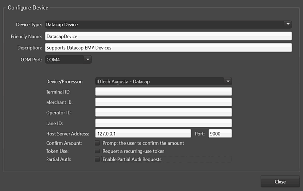
- COM Port - This dropdown contains a list of all available communications (COM) ports on the system. For serial devices (non-USB), select the COM port assigned to the device, or you can enter a new one. If you do not know what COM port a device uses, use Windows Device Manager to find it (see Bill/Cash Acceptors, I/O Boards, and Sensors, COM Port above for these steps).
- Device/Processor - Select the combination of device (type of terminal used for the transactions) and credit card processor. (See the Datacap Systems website for a list of terminal devices and processors that are supported by Datacap.)
- Merchant ID - Enter the ID of the merchant where the transaction is to be run.
- Operator ID - Enter the ID of the user at the merchant who is running the transaction.
- Lane ID - Enter the ID of lane that the operator (see above) is using to run the transaction.
- Host Server Address - Set the IP address of the server that is hosting the Datacap services.
- Port - Enter the port number for the server that is hosting the Datacap services.
- Prompt the user to confirm the amount - If checked, the user will be prompted by the terminal to confirm the transaction amount.
- Request a recurring-use token - If checked, the user can request a token that can be used indefinitely for transaction payments.
- Enable Partial Auth Requests - If checked, the user can request partial authorization for the transaction.
FreedomPay EMV
The screen looks like this when the “Device Type” dropdown is set to “FreedomPay EMV”.
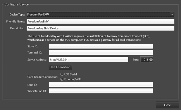
- Store ID - Set the ID for the store that is running the Freeway Commerce Connect (FCC) terminal.
- Terminal ID - An ID that is unique to the user's FCC (payment processor for these devices) account and is generated/sent to a user when that user creates an FCC account.
- Server Address - Set the IP address of the server that is hosting the FCC services.
- Port - Enter the port number for the server that is hosting the FCC service.
- Test Connection - Use this button to test the connection to FCC. A progress meter will show, followed by a popup window indicating if the test succeeded or failed.
- Card Reader Connection - Specify the type of connection to be used with the card reader (“USB/Serial” or “Ethernet/WiFi”).
- Lane ID - (Only available when “Card Reader Connection” above is set to “Ethernet/WiFi”) Enter the ID of the checkout lane that the store is using to run the transaction.
- Workstation ID - (Only available when “Card Reader Connection” above is set to “Ethernet/WiFi”) Enter the ID of the checkout workstation that the store is using to run the transaction.
Glory Front Cycle Control Currency Recycler
The screen looks like this when the “Device Type” dropdown is set to “Glory Front Cycle Control Currency Recycler”.

- Device URL - Enter the address where the currency recycler is hosted. Note: This MUST be set for KioWare to properly communicate (send commands to/receive response from) with the device.
Omron HVC Device
The screen looks like this when the “Device Type” dropdown is set to “Omron HVC Device”.
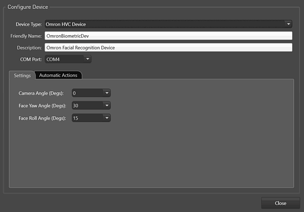
- COM Port - This dropdown contains a list of all available communications (COM) ports on the system. For serial devices (non-USB), select the COM port assigned to the device, or you can enter a new one. If you do not know what COM port a device uses, use Windows Device Manager to find it (see Bill/Cash Acceptors, I/O Boards, and Sensors, COM Port above for these steps).
Settings Tab
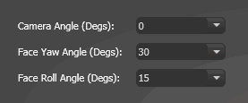
- Camera Angle (Degs) - Set the angle of the camera (options include 0, 90, 180, or 270 degrees).
- Face Yaw Angle (Degs) - Set the angle of the facial yaw (rotation around the Y axis of the face; options include 30, 60, or 90 degrees).
- Face Roll Angle (Degs) - Set the angle of the facial roll (rotation around the Z axis of the face; options include 15 or 45 degrees).
Automatic Actions Tab
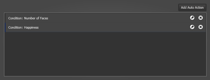
- Add Auto Action - Select this button (see image above) to add a new automatic action to the list. A popup window shows the related settings (see “Edit” below for descriptions of these settings).
- Delete (“X” icon) - Select the “X” icon (see image above) to remove an automatic action.
- Edit (pencil icon) - Select the pencil icon (see image above) to edit an automatic action. A popup window shows these settings.
- Condition Tab - Use the settings below to tell KioWare what conditions will prompt an action (as set on the Action Tab below) to be performed.
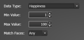
- Data Type - Select the type of data to be used for the condition (options include “Number of Faces”, “Age”, “Gender”, “Happiness”, “Anger”, “Expression Degree”, etc.). Based on your selection, different settings may show below.
- Min Value - (Unavailable when the “Data Type” above is set to “Gender”) Set a minimum value (between 0 and 100) for the “Data Type” selected above. (Facial emotions/age that are recognized by the device are then measured as values, where higher numbers indicate stronger emotions/higher age. Setting this “Min Value” and the “Max Value” below creates the range that is used to assign values.)
- Max Value - (Unavailable when the “Data Type” above is set to “Gender”) Set a maximum value (between 0 and 100) for the “Data Type” selected above. (Facial emotions/age that are recognized by the device are then measured as values, where higher numbers indicate stronger emotions/higher age. Setting the “Min Value” above and this “Max Value” creates the range that is used to assign values.)
- Gender - (Only available when the “Data Type” above is set to “Gender”) Select the gender for the “Data Type” selected above.
- Match Faces - (Only available when the “Data Type” above is not set to “Number of Faces”, “Number of Human Bodies”, or “Number of Hands”) Set how to match faces to the data in the statistics database (options include “Any” and “All”). Note: Data in the statistics database is uploaded to KioWare Server and can be viewed in the Usage Stats Reports (see Introduction, Reporting Quick Reference, Kiosk Detailed Usage Reports in the KioWare Server User Guide). For more details on statistics logging, see Kiosk Management Tab, Related Terms and Questions.
- Action Tab - Use the settings below to tell KioWare what action to complete when the conditions (as set on the Condition Tab above) are met. (See also Keyboard Filtering Tab, HotKey Entries, Edit, Action for this Item.)
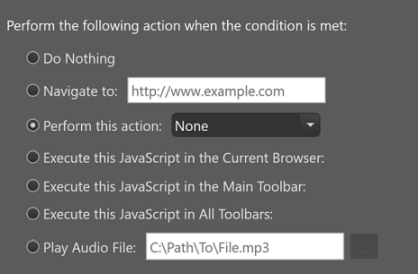
- Do Nothing - Meeting the conditions (as set on the Condition tab above) will not tell KioWare to do anything.
- Navigate To - Enter a URL or file path that KioWare will be directed to.
- Perform this Action - Select an action from a list of common actions (Back, Paste, Scroll Up, Zoom Out, etc.).
- Execute this JavaScript in the Current Browser - When selected and JavaScript is entered in the pane that shows, KioWare will run the JavaScript command to complete the related action in the currently displayed browser window.
- Execute this JavaScript in the Main Toolbar - When selected and JavaScript is entered in the pane that shows, KioWare will run the JavaScript command to complete the related action in the currently displayed toolbar.
- Execute this JavaScript in All Toolbars - When selected and JavaScript is entered in the pane that shows, KioWare will run the JavaScript command to complete the related action in the currently displayed toolbar and in all other available toolbars.
- Play Audio File - When selected and both a file path and element ID for the audio file are entered in the boxes that show, KioWare will play the audio file. (When using the ellipsis button at the right to find and select a file, the file path will show in the top box.)
Numato General Purpose IO Board
The screen looks like this when the “Device Type” dropdown is set to “Numato General Purpose IO Board”.
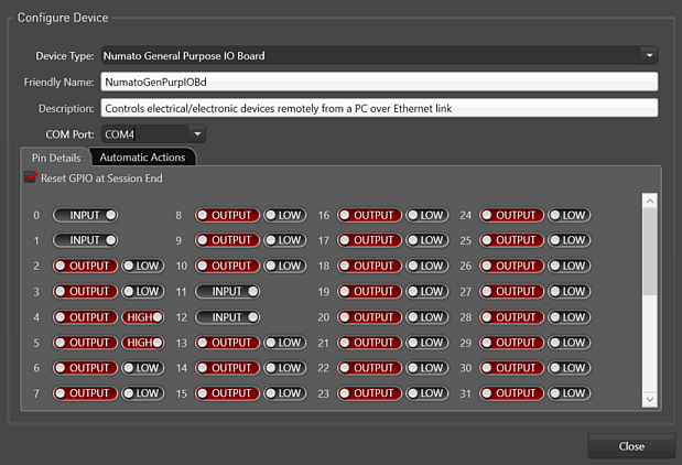
- COM Port - This dropdown contains a list of all available communications (COM) ports on the system. For serial devices (non-USB), select the COM port assigned to the device, or you can enter a new one. If you do not know what COM port a device uses, use Windows Device Manager to find it (see Bill/Cash Acceptors, I/O Boards, and Sensors, COM Port above for these steps).
Pin Details Tab
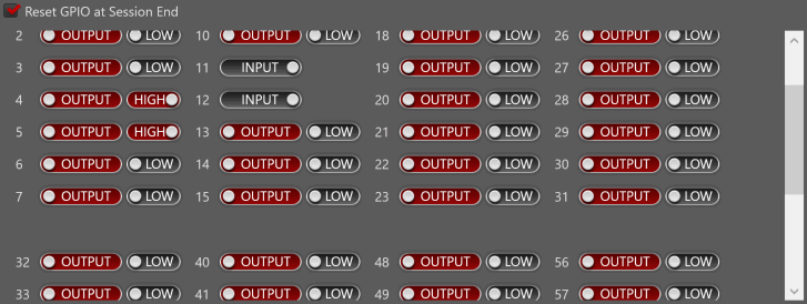
- Reset GPIO at Session End - If checked, all pins will be reset to their default input/output (IO) and voltage states when a user session ends (i.e., output and low-voltage states).
- General Purpose IO Pins - Set how each of the 64 pins will be controlled (see image above).
- IO Toggle - Sets the default IO state of all pins. All pins default to the output state (appears as “OUTPUT”), but you can select the toggle and change the pin to an input state (label changes to “INPUT”).
- Voltage Toggle - (Only applies to pins whose “Default IO State” is set to “OUTPUT”; see above) Sets the default voltage state of pins. All output pins default to the low-voltage state (appears as “LOW”), but you can select the toggle and change the pin to a high-voltage state (appears as “HIGH”).
Automatic Actions Tab
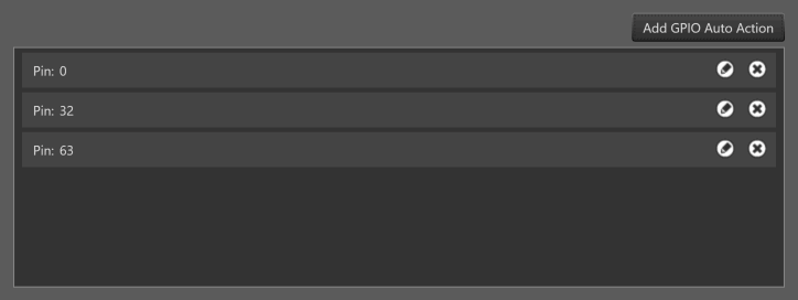
- Add New Automatic Action - Select the “Add GPIO Auto Action” button (see image above) to add a new automatic action. The automatic action will show in the pane below (see “Edit Automatic Action” below for descriptions of settings that can be customized).
- Reorder Automatic Action - Select and drag an automatic action entry to reorder it.
- Remove Automatic Action - Select the “X” icon (see image above) to remove an automatic action.
- Edit Automatic Action - Select the pencil icon (see image above) to edit automatic action settings (see images below):
- Pin Details Tab - This tab (see image below) sets the conditions that must be met in order for the automatic action to occur (as set on the Action Tab below).
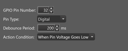
- GPIO Pin Number - Select the number that identifies the pin (as shown on the Pin Details Tab above; range is 0–63).
- Pin Type - Select the pin type (“Digital” or “Analog”).
- Debounce Period - After the automatic action is triggered, the amount of time (in milliseconds) that must pass before the action can be triggered again.
- Action Condition - (Applies only to output pins) Select the condition of the pin that will trigger the automatic action to occur (“When Pin Voltage Goes Low” or “When Pin Voltage Goes High”).
- Action Tab - Use this tab (see image below) to tell KioWare what action to complete when the conditions (as set on the Pin Details Tab above) are met. (See also Keyboard Filtering Tab, HotKey Entries, Edit, Action for this Item.)
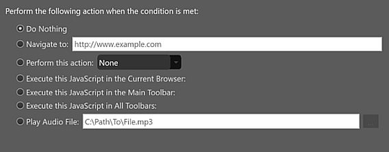
- Do Nothing - Meeting the conditions (as set on the Pin Details Tab above) will not tell KioWare to do anything.
- Navigate To - Enter a URL or file path that KioWare will be directed to.
- Perform this Action - Select an action from a list of common actions (Back, Paste, Scroll Up, Zoom Out, etc.).
- Execute this JavaScript in the Current Browser - When selected and JavaScript is entered in the pane that shows, KioWare will run the JavaScript command to complete the related action in the currently displayed browser window.
- Execute this JavaScript in the Main Toolbar - When selected and JavaScript is entered in the pane that shows, KioWare will run the JavaScript command to complete the related action in the currently displayed toolbar.
- Execute this JavaScript in All Toolbars - When selected and JavaScript is entered in the pane that shows, KioWare will run the JavaScript command to complete the related action in the currently displayed toolbar and in all other available toolbars.
- Play Audio File - When selected and both a file path and element ID for the audio file are entered in the boxes that show, KioWare will play the audio file. (When using the ellipsis button at the right to find and select a file, the file path will show in the top box.)
Shift4 EMV
The screen looks like this when the “Device Type” dropdown is set to “Shift4 EMV”.
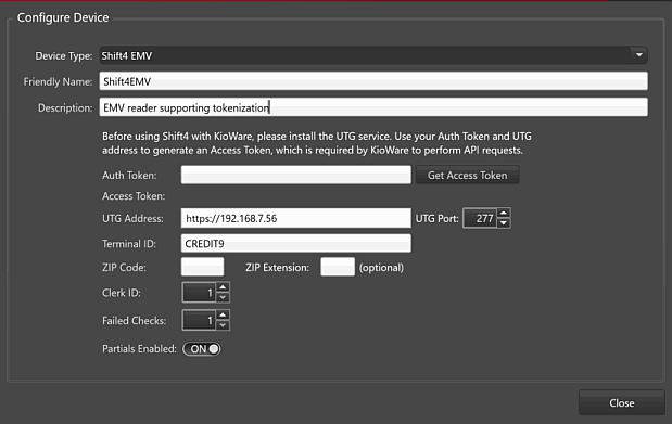
- Auth Token - Enter the Auth Token (unique code provided by Shift4 during the certification process).
Note: When integrating with the Shift4 application programming interface (API), the Shift4 Payments API team will provide you with an Auth Token during the certification process. For certification and production, the Auth Token must be exchanged for an Access Token (see below).
- Get Access Token - Once the “Auth Token” is entered above, use this button to obtain the Access Token, which will show below.
- Access Token - (Read-Only) Shows the Access Token.
- UTG Address - Enter the address for the Universal Transaction Gateway [or UTG, Shift4's payment application that encrypts and securely transmits transaction data from point-of-sale (POS) systems to payment processors and card authorization services (default is https://127.0.0.1)].
- UTG Port - Port used to log onto the UTG (default is 277).
- Terminal ID - An ID that is unique to the Shift4 token-processing terminal.
- Zip Code - Enter the zip code of the location housing the Shift4 terminal.
- Zip Extension - (Optional) Enter the 4-digit zip code extension.
- Clerk ID - Set the ID for the clerk that is running the Shift4 terminal (default is 1).
- Failed Checks - Set the maximum number of failed health checks that can occur before the device switches to an “Offline” status (default is 1). Note: When a health check or attempted transaction is successful, this counter will automatically reset to zero and the device will show an “Ok” status.
- Partials Enabled - If set to “ON”, the user can request partial authorization for the transaction.
Tenerum EMV
The screen looks like this when the “Device Type” dropdown is set to “Tenerum EMV”.
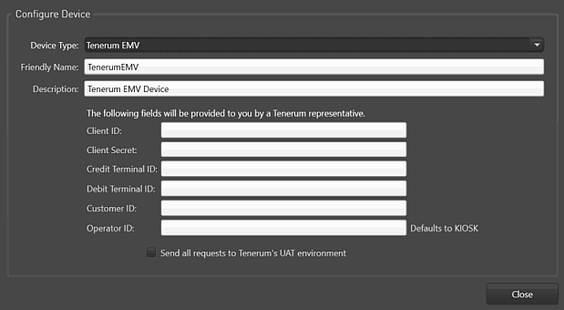
The following will be provided to you by a Tenerum (payment processor for this device) representative after creating an account.
- Client ID - Enter your Tenerum client ID [for accessing the Tenerum application programming interface (API)].
- Client Secret - Enter the Tenerum client secret (unique ID number that Tenerum gives to users who want to do custom programming using its API).
- Credit Terminal ID - An ID that is unique to your Tenerum credit-processing terminal.
- Debit Terminal ID - An ID that is unique to your Tenerum debit-processing terminal.
- Customer ID - Enter your Tenerum customer ID.
- Operator ID - Enter a unique ID for your kiosk that is running Tenerum (can be any value; defaults to KIOSK if left blank).
- Send all requests to Tenerum's UAT environment - If checked, all transaction requests will be sent through Tenerum's user acceptance testing environment (to test them in real-world scenarios).
Wattbox Power Controller
The screen looks like this when the “Device Type” dropdown is set to “Wattbox Power Controller”.
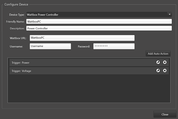
- Wattbox URL - Enter the URL of the Wattbox web interface.
- Username - Enter the username to log onto the Wattbox web interface.
- Password - Enter the password to log onto the Wattbox web interface.
- Add Auto Action - Select this button (see image above) to add a new automatic action. A popup window displays the automatic action settings (see Condition Tab and Action Tab below for descriptions of these settings).
- Remove Auto Action (“X”) - Select the “X” icon (see image above) to remove an automatic action
- Edit Auto Action (pencil icon) - Select the pencil icon (see image above) to edit automatic action settings (see Condition Tab and Action Tab below).
Condition Tab
This tab sets the conditions that must be met in order for the automatic action to occur (as set on the Action Tab below).
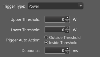
- Trigger Type - Specify the electrical measurement that will trigger the automatic action to occur (options are “Voltage”, “Current”, and “Power”).
- Upper Threshold - Set the highest value that the “Trigger Type” (see above) can have before the automatic action is triggered.
- Lower Threshold - Set the lowest value that the “Trigger Type” (see above) can have before the automatic action is triggered.
- Trigger Auto Action - Specify the condition of the “Trigger Type” (see above) threshold range (as entered in “Upper Threshold” and “Lower Threshold” above) that will trigger the automatic action to occur.
- Outside Threshold - The “Trigger Type” (see above) goes outside the specified range.
- Inside Threshold - The “Trigger Type” (see above) goes inside the specified range.
- Debounce - The amount of time (in milliseconds) during which the device has time to recover and re-enter the allowed range. If the device recovers, the auto-action will not occur.
Action Tab
This tab sets up the automatic action that will occur when the specified conditions are met (as set on Condition Tab above). (See also Keyboard Filtering Tab, HotKey Entries, Edit, Action for this Item.)
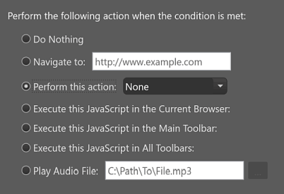
- Do Nothing - Meeting the conditions (as set on the Condition Tab above) will not tell KioWare to do anything.
- Navigate To - Enter a URL or file path that KioWare will be directed to.
- Perform this Action - Select an action from a list of common actions (Back, Paste, Scroll Up, Zoom Out, etc.).
- Execute this JavaScript in the Current Browser - When selected and JavaScript is entered in the pane that shows, KioWare will run the JavaScript command to complete the related action in the currently displayed browser window.
- Execute this JavaScript in the Main Toolbar - When selected and JavaScript is entered in the pane that shows, KioWare will run the JavaScript command to complete the related action in the currently displayed toolbar.
- Execute this JavaScript in All Toolbars - When selected and JavaScript is entered in the pane that shows, KioWare will run the JavaScript command to complete the related action in the currently displayed toolbar and in all other available toolbars.
- Play Audio File - When selected and both a file path and element ID for the audio file are entered in the boxes that show, KioWare will play the audio file. (When using the ellipsis button at the right to find and select a file, the file path will show in the top box.)
Recyclers, Readers, and Other Devices
The screen looks like this (or similar to this) when the “Device Type” dropdown is set to one of the following: “Code Corp Command Driven Barcode Device”, “Identive RF Tag Device”, “MagTek Excella Check Reader”, “MagTek ImageSafe Check Reader”, “MEI Banknote Recycler (BNR)”, “OTI Reader”, “Tanvas Touch Display”, or “Xtreme Power UPS (J60)”.
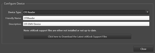
- Click Here to Download the Latest OtiKiosk Support Files - (Only applicable to OTI readers) Select this button to download the most up-to-date OtiKiosk files that support use of these devices. Note: This button only shows when the latest OtiKiosk files have NOT been downloaded. If files have been downloaded, a message indicates that the files are installed (see image above).
Reader, Imaging, and Other Devices
The screen looks like this (or similar to this) when the “Device Type” dropdown is set to one of the following: “Access IS-Passport Reader”, “Code Barcode Reader”, “Digital Logic RF Tag Device”, “DigitalPersona Fingerprint Scanner”, “Elatec TWN4 Id/Storage Tag Device”, “E-Seek M500 Id Scanner”, “FEIG OBID Id/Storage Tag Device”, “Generic Keyboard Wedge Device”, “MagTek HID MSR”, “Opticon Barcode Reader”, “Raw SCard Id/Storage Tag Device”, “RF Ideas Proximity Card Reader”, “ScanShell OCR Device”, “Symbol SNAPI”, “Twain Imaging Device”, or “WIA Imaging Device”.
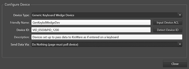
- Input Device ACL - Select this button to set the access list for input devices (see Device Access List Configuration Screen below).
- Device ID - (Only available if “Generic Keyboard Wedge Device” is selected in the “Device Type” dropdown) Enter the unique vendor ID/product ID combination (in the format of VID_[vendor ID]&PID_[product ID], such as VID_05E0&PID_1200) if you know which device is in use. If the device is not known, then use the “Detect Device ID” button to tell KioWare to listen for and detect input (the result of a scan) from the device. The device ID that KioWare detects input from will automatically show in this box.
- COM Port - (Only available if “Code Barcode Reader”, “Digital Logic RF Tag Device”, “FEIG OBID Id/Storage Tag Device”, or “Opticon Barcode Reader” is selected in the “Device Type” dropdown) This dropdown contains a list of all available communications (COM) ports on the system. For serial devices (non-USB), select the COM port assigned to the device, or you can enter a new one. If you do not know what COM port a device uses, use Windows Device Manager to find it (see Bill/Cash Acceptors, I/O Boards, and Sensors, COM Port above for these steps).
- Send Data Via - Tells KioWare how users should be notified when input device data is ready to be retrieved (see Notifying Users About Input Device Data below).
Device Access List Configuration Screen
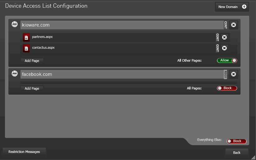
When you select the “Input Device ACL” button on the Configure Device window, this screen shows.
Setting Up Your List
Select the “New Domain” button to add a new domain and any related pages to the device access list. These settings will show (see image above).
- Domain Name (unlabeled) - Enter the new domain. Do NOT include beginning protocols (e.g., “http://” or “https://”).
- CONT - Select this icon to set matching for regular expressions (“REGX” label) or for CONTAINS matching (“CONT” label). (For more details on regular expressions and CONTAINS matching, see Browser Tab, Related Terms and Questions.)
- Add Page - Select this button to add a new web page to the domain.
- Page Name (unlabeled) - Enter the new web page for the domain.
- Block - Use this button to set how this web page should be handled by your device (allow or block input from it). Pages that are blocked show a red icon to the left, and pages that are allowed show a green icon.
- CONT - Select this icon to set matching for regular expressions (“REGX” label) or for CONTAINS matching (“CONT” label). (For more details on regular expressions and CONTAINS matching, see Browser Tab, Related Terms and Questions.)
- All Pages Block and All Other Pages Block - Select these buttons to set how your device should handle an entire domain or web pages that are not added under a domain (allow or block input from them). The button will be labeled “All Pages Block” if no pages are added to a domain, and will appear as “All Other Pages Block” when web pages are added.
- Everything Else - Select this button to set how your device should handle all other domains and web pages that are not in your device access list (allow or block input from them).
Changing Your List
On the Device Access List Configuration screen (see image above), select any textbox or dropdown menu and make changes. KioWare will automatically save your changes.
Removing Domains/Pages In Your List
“X” icons appear to the right of domain and page entries (see image above). Select any “X” icon to remove a domain or web page. Icons to the far right are for domains, and indented icons are for pages. Note: Removing an entire domain will also remove settings for all pages within that domain.
Messages and Logs for Blocked Domains/Pages
Select the “Restriction Messages” button (see image above) to set options for blocking and creating Event Logs. These settings will show.
- Log Blocked Matches - If checked, any attempts by your device to visit domains or web pages that you told KioWare to block (see above) will create Windows Application Event Logs.
- Do NOT Block - If checked, KioWare will not block your device from accessing any domains or web pages, regardless if you told KioWare to block them (see above). Note: This setting gives you the lowest amount of security for your devices and should only be used for testing purposes.
- Show Block Message - If checked, enter a block message in the box below. Any attempts by your device to visit domains or web pages that you told KioWare to block (see above) will show this message, to alert users that device blocking has occurred.
- Show URL in Block Message - If checked, the web address of the blocked domain or web page that you tried to visit will appear below the block message.
Notifying Users About Input Device Data
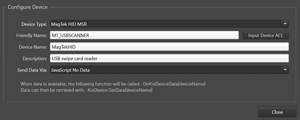
In the “Send Data Via” dropdown, there are four ways to notify users that data is ready to be retrieved from input devices: “JavaScript No Data”, “JavaScript With Data”, “Navigate w/ Device Name”, and “HTML Form Fill”. Or, select the “Do Nothing (page must poll device)” option if you do not want users to be notified.
Using JavaScript Without Data
When you select the “JavaScript No Data” option in the “Send Data Via” dropdown, the Configure Device window looks like this.
Using JavaScript With Data
When you select the “JavaScript With Data” option in the “Send Data Via” dropdown, the Configure Device window looks like this.
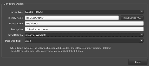
- Data Encoding - Select the type of encoding (converts data to a format used with computer applications) to be used when sending data.
- Hex - Hexadecimal (coding has a base of 16, includes 0–9, and also uses A–F to represent 10–15).
- UTF8 - 8-bit Unicode Transformation Format (variable-width character coding using 1–4 8-bit bytes; preferred for email and web pages).
- ASCII - American Standard Code for Information Interchange (represents 128 uppercase/lowercase English letters, numbers, and punctuation symbols as numeric codes).
- Base 64 - Base64 [encoding/decoding technique used to convert ASCII text format to binary data (only uses 1 and 0) and vice-versa].
Using Device Name
When you select the “Navigate w/ Device Name” option in the “Send Data Via” dropdown, the Configure Device window looks like this.
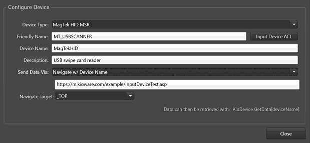
- Navigate URL - Tells KioWare the web page to go to for inputting the data.
- Navigate Target - (Optional) Tells KioWare that you are passing data to a window or frame contained in the web page entered above. The _TOP and _BLANK parameters appear in the dropdown for convenience, but any valid window or frame name can also be entered.
Using HTML Form Fill
When you select a magnetic stripe reader (MSR) device and also select the “HTML Form Fill” option in the “Send Data Via” dropdown, the Configure Device window looks like this.
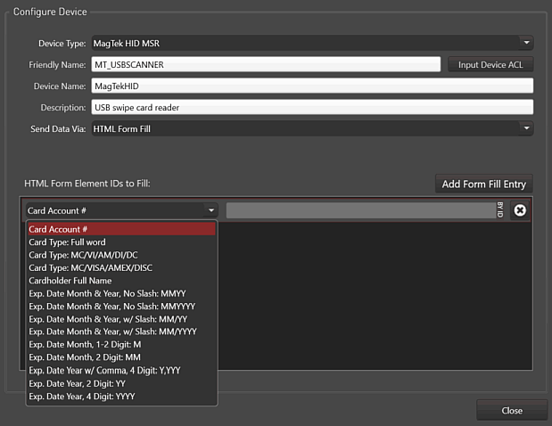
- Add Form Fill Entry - Select this button to add a new HTML form fill element (will be auto-filled on a web page form based on credit card information).
- HTML Form Fill Element (unlabeled) - Select the HTML form fill element from the dropdown.
- Card Account # - Card number.
- Card Type: Full Word - Card type (MasterCard, Visa, Amex, Discover, Diners Club).
- Card Type: MC/VI/AM/DI/DC - Dropdown with values (MasterCard=MC, Visa=VI, Amex=AM, Discover=DI, Diners Club=DC).
- Card Type: MC/VISA/AMEX/DISC - Dropdown with values (MasterCard=MC, Visa=VISA, Amex=AMEX, Discover=DISC).
- Cardholder Full Name - Card holder's name.
- Exp. Date Month & Year, No Slash: MMYY - Dropdown with values for 2-digit expiration month and 2-digit expiration year (e.g., if Jan-Dec=01-12, month=Jan, and year=2020, then value=0120).
- Exp. Date Month & Year, No Slash: MMYYYY - Dropdown with values for 2-digit expiration month and 4-digit expiration year (e.g., if Jan-Dec=01-12, month=Jan, and year=2020, then value=012020).
- Exp. Date Month & Year, w/ Slash: MM/YY - Dropdown with values for 2-digit expiration month and 2-digit expiration year separated by a slash (e.g., if Jan-Dec=01-12, month=Jan, and year=2020, then value=01/20).
- Exp. Date Month & Year, w/ Slash: MM/YYYY - Dropdown with values for 2-digit expiration month and 4-digit expiration year separated by a slash (e.g., if Jan-Dec=01-12, month=Jan, and year=2020, then value=01/2020).
- Exp. Date Month, 1-2 Digit: M - Dropdown with values for 1-digit or 2-digit expiration month (e.g., if Jan-Dec=01-12 and month=Jan, then Jan value=1, without beginning zero; but if month=Dec, then Dec value=12).
- Exp. Date Month, 2 Digit: MM - Dropdown with values for 2-digit expiration month (e.g., if Jan-Dec=01-12 and month=Jan, then Jan value=01).
- Exp. Date Year w/ Comma, 4 Digit: Y,YYY - Dropdown with values for 4-digit expiration year with comma (e.g., if year=2020, then year value=2,020).
- Exp. Date Year, 2 Digit: YY - Dropdown with values for 2-digit expiration year (e.g., if year=2020, then year value=20).
- Exp. Date Year, 4 Digit: YYYY - Dropdown with values for 4-digit expiration year (e.g., if year=2020, then year value=2020).
- Field ID/CSS Selector (unlabeled) - Enter either the ID (name) of the corresponding form field (e.g., text entry box or dropdown box) on your web page, or a Cascading Style Sheet (CSS) selector (see below).
- By ID/Select - When the “BY ID” label shows, KioWare will auto-fill this field on your web page by matching its ID to that of the corresponding form fill element entered above. To tell KioWare to auto-fill the field by using CSS selectors, select the “BY ID” label. The label will then appear as “SELECT”.
- Delete (“X” icon) - Select this icon to remove a form fill element.
Output Devices
The screen looks like this (or similar to this) when any output device is selected in the “Device Type” dropdown.
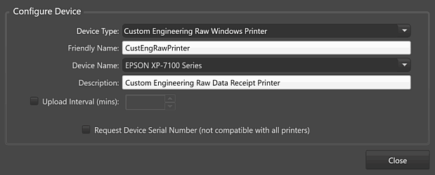
- Add Output Device - Select this button to add a new output device. These settings will show.
Note: If also using KioWare Server, the “Friendly Name” (see below) and status of all output devices will be included in heartbeat data that is sent to the server (see Kiosk Management, Reports Tab, Heartbeat Report in the KioWare Server User Guide).
- Device Type - Select the type of output device connected to your kiosk or computer. (See table below for a list of supported device types.)
- Friendly Name - Enter the name used by KioWare JavaScript functions to identify a device entry in the KioWare list.
- Device Name - (Only available when certain devices are selected under “Device Type” above) The name that KioWare uses (on the back end) to identify the physical device with the underlying device-specific application programming interfaces (APIs). Select a printer name from this dropdown box, or select the “<Auto Detect Name>” option to allow KioWare to auto-detect the name.
- Description - Enter a description for the device being used.
- Upload Interval (mins) - If checked, KioWare will upload the device status for the specified device on the interval that is set (in minutes; default is 10). KioWare will try to upload device status three times before it stops trying and logs an error in the Event Log (for more details on Event Logs, see Browser Tab, Related Terms and Questions).
- Request Device Serial Number - (Only available when “Device Type” above is set to “Custom Engineering Raw Windows Printer”) If checked and also using KioWare Server, the printer's serial number will be included in heartbeat data that is sent to the server (see Kiosk Management, Reports Tab, Heartbeat Report in the KioWare Server User Guide).
- COM Port - (Only available for certain output devices; see below) This dropdown contains a list of all available communications (COM) ports on the system. For serial devices (non-USB), select the COM port assigned to the device, or you can enter a new one. If you do not know what COM port a device uses, use Windows Device Manager to find it (see Input Devices, Bill/Cash Acceptors, I/O Boards, and Sensors, COM Port above for these steps).
Note: The above setting is only available when any of the following is selected in the “Device Type” dropdown: “Cust. Eng. KPM-302-H Printer and RF Tag R/W (Svelta)”, “Custom Engineering KPM216 Printer”, “Custom Engineering KPM302 Printer (Svelta)”, “Epson ESC/POS Serial Printer”, “Glory Currency Dispenser”, “LG CDM Currency Dispenser”, “Puloon ECDM Currency Dispenser”, “Puloon LCDM 1000 Currency Dispenser”, “Puloon LCDM 2000 Currency Dispenser”, “Puloon LCDM 4000 Currency Dispenser”, “Puloon VCDM Currency Dispenser”, “Stimare STIMA Printer”, “Stimare STIMA Printer and RF Tag R/W”, or “TeleQuip Coin Dispenser”.
- Click Here to Download the Latest Envoy Support Files - (Only applicable to “Fujitsu F53 (via ARCA Envoy)” device type) Select this button to download the most up-to-date Envoy files that support use of the Fujitsu F53.
- Edit (pencil icon) - Select this icon to change an output device.
- Delete (“X” icon) - Select this icon to remove an output device.
| Supported Output Device Types* |
- Boca Printer
- Custom Eng. KPM302-H Printer and RF Tag R/W (Svelta)
- Custom Engineering KPM216 Printer
- Custom Engineering KPM302 Printer (Svelta)
- Custom Engineering Raw Windows Printer
- Epson ESC/POS Serial Printer
- Fujitsu F53 (via ARCA Envoy)
- Glory Currency Dispenser
- Hengstler C-56 Printer
|
- LG CDM Currency Dispenser
- Nippon Primex NP3511 Printer
- Pac Boards API
- Puloon ECDM Currency Dispenser
- Puloon LCDM 1000 Currency Dispenser
- Puloon LCDM 2000 Currency Dispenser
- Puloon LCDM 4000 Currency Dispenser
- Puloon VCDM Currency Dispenser
- Sankyo SHT610 Card Dispenser
|
- Star Micronics Printer
- Star Micronics Printer in ESC/POS Mode
- Stimare STIMA Printer
- Stimare STIMA Printer and RF Tag R/W
- Telequip Coin Dispenser
- Zebra Direct USB Printer
- Zebra KR403 Printer
- Zebra TTP (Spooled) Printer
- Zebra ZD420 Printer
-
|
- * For specific devices that fall under these device types, visit the Devices page of the KioWare website.
Monitored Devices
The settings below will show when any monitored device (device monitored by KioWare Server) is selected in the “Device Type” dropdown. For specific screen images, see the subsections below.
- Add Monitored Device - Select this button to add a new monitored device. These settings will show.
Note: If also using KioWare Server, the “Friendly Name” (see below) and status of all monitored devices will be included in heartbeat data that is sent to the server (see Kiosk Management, Reports Tab, Heartbeat Report in the KioWare Server User Guide).
- Device Type - Select the type of monitored device connected to your kiosk or computer. (See table below for a list of supported device types; see sections below for specific device type settings).
- Friendly Name - Enter the name used by KioWare JavaScript functions to identify a device entry in the KioWare list.
- Device Name - (Only available when certain devices are selected under “Device Type” above) The name that KioWare uses (on the back end) to identify the physical device with the underlying device-specific application programming interfaces (APIs). Select a printer name from this dropdown box, or select the <Auto Detect Name> option to allow KioWare to auto-detect the name.
- Description - Enter a description for the device being used.
- Upload Interval (mins) - If checked, KioWare will upload the device status for the specified device on the interval that is set (in minutes; default is 10). KioWare will try to upload device status three times before it stops trying and logs an error in the Event Log (for more details on Event Logs, see Browser Tab, Related Terms and Questions).
- Other Settings - All other possible settings on this window are described in the individual sections below.
- Edit (pencil icon) - Select this icon to change a monitored device.
- Delete (“X” icon) - Select this icon to remove a monitored device.
| Supported Monitored Device Types* |
- Citizen Printer
- Custom Engineering Printer
- DLP Design DLP-TH1
- Geolocation
- Hardware Fan Speed
|
- Hardware Monitor (Custom)
- Hardware Temperature
- Machine Information
- Omron Environment Sensor
- PJL Printer
|
- Practical Automation Printer
- System Battery
- Watchport T/H
|
- * For specific devices that fall under these device types, visit the Devices page of the KioWare website.
Print Job Language Printers
See also Config Tool Menu, Printer Language Monitor and Printing under the Configuration Tool section of this user guide.
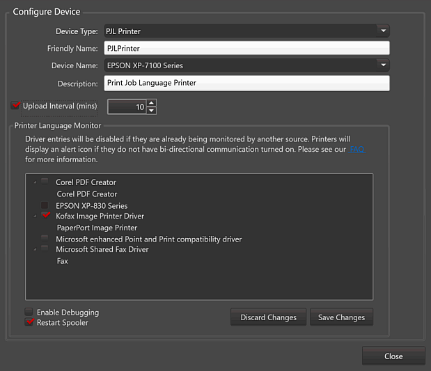
The screen looks like this when the “Device Type” dropdown is set to “PJL Printer”.
Printer Language Monitor
The box below shows all printers currently connected to the kiosk or computer. Entries that are disabled are already being monitored by another source. A warning symbol indicates that a printer's bi-directional communication is turned off. Select those printers to be monitored (a red checkmark will show), choose settings for enabling/disabling debugging and spooler restart (see below), and then select the “Save Settings” button.
- Enable Debugging - Toggles a debug log (kioprmon_log.txt) that is written to the Windows system32 directory. This log is for debugging purposes only; most users will never enable it because the file can become infinitely large.
- Restart Spooler - If checked, the print spooler will be restarted during PJL monitoring.
Receipt, Thermal, and Other Printers
The screen looks like this (or similar to this) when the “Device Type” dropdown is set to “Citizen Printer”, “Custom Engineering Printer”, or “Practical Automation Printer”.
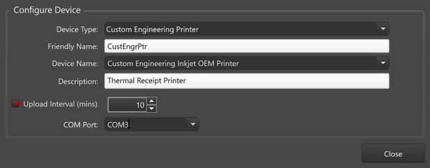
- COM Port - (Only available if “Custom Engineering Printer” is selected in the “Device Type” dropdown) This dropdown contains a list of all available communications (COM) ports on the system. For serial devices (non-USB), select the COM port assigned to the device, or you can enter a new one. If you do not know what COM port a device uses, use Windows Device Manager to find it (see Input Devices, Bill/Cash Acceptors, I/O Boards, and Sensors, COM Port above for these steps).
Omron Environment Sensor
The screen looks like this when the “Device Type” dropdown is set to “Omron Environment Sensor”.
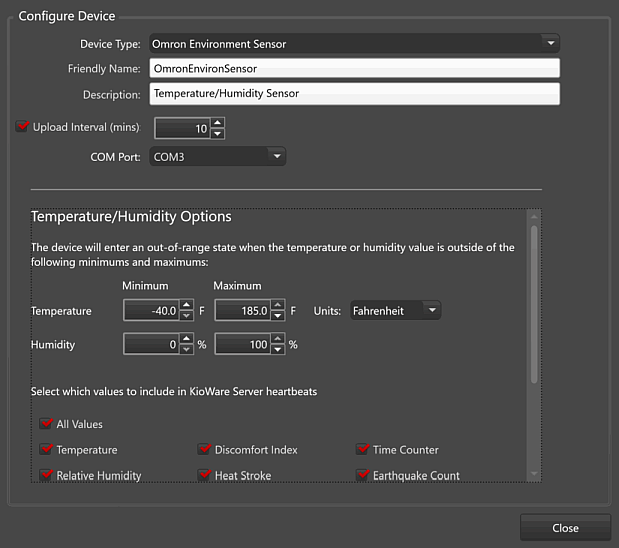
- COM Port - This dropdown contains a list of all available communications (COM) ports on the system. For serial devices (non-USB), select the COM port assigned to the device, or you can enter a new one. If you do not know what COM port a device uses, use Windows Device Manager to find it.
- Temperature Minimum and Maximum - Enter the minimum and maximum temperatures that a device can operate at before the temperature status changes (up to 4 decimal places). Once the device's temperature falls outside of one of these values, it will enter an out-of-range state and can no longer be shown.
- Units - Set the unit of temperature (Celsius or Fahrenheit).
- Humidity Minimum and Maximum - Enter the minimum and maximum humidity levels that a device can operate at before the humidity status changes. Once the device's humidity falls outside of one of these values, it will enter an out-of-range state and can no longer be shown.
-
KioWare Server Heartbeat Values - Scroll down and check the boxes for the values you want to include in KioWare Server heartbeats (see Kiosk Management, Reports Tab, Heartbeat Report in the KioWare Server User Guide). To include all values, check the “All Values” checkbox.
-
| Temperature | The real-time temperature of the device |
| Relative Humidity | The real-time humidity of the device |
| Ambient Light | The real-time light intensity of the device |
| Barometric Pressure | The real-time barometric pressure of the device |
| Sound Noise | The real-time noise intensity of the device |
| eTVOC | eTVOC (equivalent Total Volatile Organic Compounds) refers to the total concentration of volatile organic compounds in a room environment. |
| eCO2 | Equivalent Carbon Dioxide level. Represents the level of greenhouse gases in the air. |
| Discomfort Index | Expresses the heat and humidity of summer in a quantitative manner. It is calculated from
temperature and humidity (see above). |
| Heat Stroke | Expresses the risk of heat stroke in a quantitative manner. It is calculated from temperature and humidity (see above). |
| Calculated Vibration Info | Vibration measures calculated from the raw acceleration data (includes SI value, PGA, and seismic intensity; see below) |
| SI Value | An index that expresses the effect a certain vibration has on a structure. It has a correlation with seismic intensity (see below). |
| PGA | Peak acceleration value of a certain interval (due to earthquake) |
| Seismic Intensity | A value correlated with seismic intensity that is calculated from the SI value (see above) |
| Accel Data | Acceleration measurement data |
| Time Counter | Represents elapsed time since the device started recording data |
| Earthquake Count | The number of earthquakes that occurred |
| Vibration Count | The number of vibration events that occurred |
| Acceleration Vibration Data | Indicates whether an earthquake or vibration event occurred |
| Max Acceleration | Peak acceleration value along each axis |
| SI Value Axis | The axis along which the SI value (see above) is calculated |
| Acceleration Offset | The offset used for calibrating the acceleration sensor |
Other Temperature/Humidity Sensors
The screen looks like this (or similar to this) when the “Device Type” dropdown is set to “DLP Design DLP-TH1” or “Watchport T/H”.
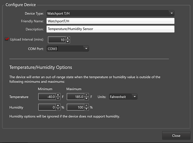
- COM Port - (Only available if “Watchport T/H” is selected in the “Device Type” dropdown) This dropdown contains a list of all available communications (COM) ports on the system. For serial devices (non-USB), select the COM port assigned to the device, or you can enter a new one. If you do not know what COM port a device uses, use Windows Device Manager to find it.
- Temperature Minimum and Maximum - Enter the minimum and maximum temperatures that a device can operate at before the temperature status changes (up to 4 decimal places). Once the device's temperature falls outside of one of these values, it will enter an out-of-range state and can no longer be shown.
- Units - Set the unit of temperature (Celsius or Fahrenheit).
- Humidity Minimum and Maximum - (Available with Watchport/H and some DLP devices; will be ignored if the device does not support humidity) Enter the minimum and maximum humidity levels that a device can operate at before the humidity status changes. Once the device's humidity falls outside of one of these values, it will enter an out-of-range state and can no longer be shown.
Hardware
The KioWare Config Tool provides options for setting up a few devices for monitoring hardware (including temperature, fan speed, and custom hardware monitoring). The sections below provide setups for specific devices.
Hardware Temperature and Fan Speed
The screen looks like this (or similar to this) when the “Device Type” dropdown is set to “Hardware Temperature” or “Hardware Fan Speed”.
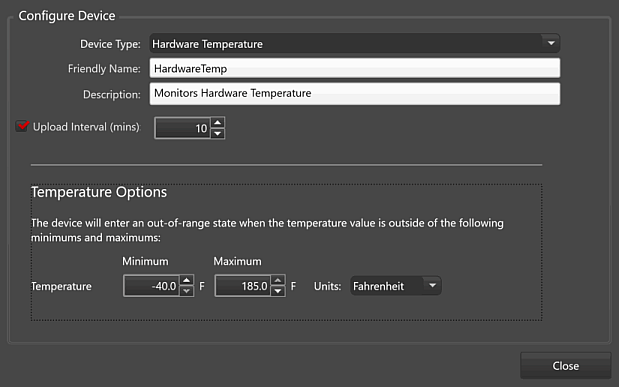
- Temperature Minimum and Maximum - Enter the minimum and maximum temperatures that a device can operate at before the temperature status changes (up to 4 decimal places). Once the device's temperature falls outside of one of these values, it will enter an out-of-range state and can no longer be shown.
- Units - Set the unit of temperature (Celsius or Fahrenheit).
Hardware Monitor (Custom)
The screen looks like this when the “Device Type” dropdown is set to “Hardware Monitor (Custom)”.
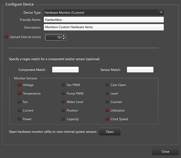
- Regex Match - (Optional) Used to specify a regex (regular expression) match for a component and/or sensor. (For more information on regular expressions, see Browser Tab, Related Terms and Questions).
- Component Match - Enter a component to be matched.
- Sensor Match - Enter a sensor to be matched.
- Monitor Sensors - Check the boxes for the internal system sensors that you want to turn on.
-
| Voltage | Monitors the real-time voltages of system items (e.g., processors) |
| Temperature | Monitors the real-time temperature of system items (e.g., processors, graphics card) |
| Fan | Monitors the real-time fan wind speed of system items (e.g., cooling fan) |
| Current | Monitors the real-time current (in amperes) of system items (e.g., processors, CPU) |
| Power | Monitors the real-time electric power (in kilowatts) of system items |
| Fan PWM | Monitors the pulse-width-modulation (PWM) controller for system fans (e.g., some motherboards contain software that regulates fans) |
| Pump PWM | Monitors the pulse-width-modulation (PWM) controller for system pumps |
| Water Level | Monitors the real-time water levels of system items |
| Position | Monitors the real-time position of system items |
| Capacity | Monitors the real-time stored electric charge of system items |
| Case Open | Monitors the real-time status of the PC enclosure (side panel), if available |
| Level | Monitors the real-time levels of system items (e.g., volume, battery) |
| Counter | Monitors the real-time counts of system counters |
| Utilization | Monitors the real-time percentage that system items (e.g., memory, processors, CPU, and disk space) are currently being used |
| Clock Speed | Monitors the real-time speed (in megahertz) of all system clocks |
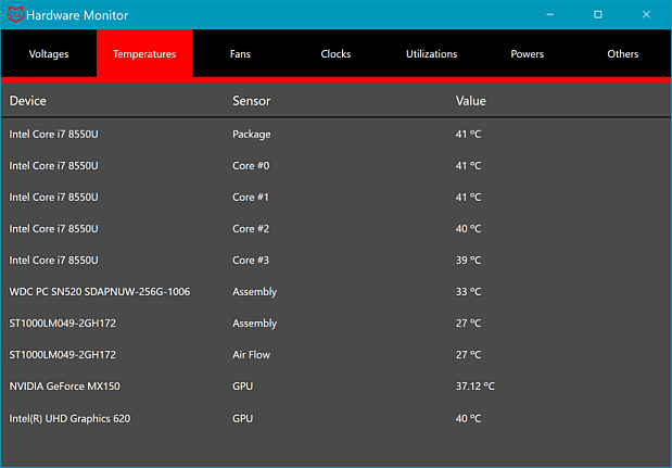
- Open - Select this button to open the hardware monitor utility. This will show the values/quantities of sensors in your machine as you set up the device (see image below).
Machine Information
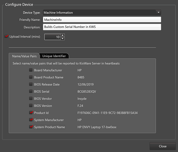
The screen looks like this when the “Device Type” dropdown is set to “Machine Information”.
Name/Value Pairs
Select the name/value pairs that will be reported to KioWare Server in heartbeats (see Kiosk Management, Reports Tab, Heartbeat Report in the KioWare Server User Guide).
- Board Manufacturer - Manufacturer of the computer's motherboard.
- Board Product Name - Product name of motherboard used in the computer.
- BIOS Release Date - Your computer's Basic Input/Output System (BIOS) release date.
- BIOS Serial - Your computer's BIOS serial number.
- BIOS Vendor - Your computer's BIOS vendor.
- BIOS Version - Your computer's BIOS version.
- Product Id - Device ID number.
- System Manufacturer - Manufacturer of the computer.
- System Product Name - Make and model of the computer.
Unique Identifier
Select the specifications to use in “building” the device serial number for use with the KioWare Server product.
Note: If also using KioWare Server, this “built” serial number will be added as an MTBF device and will be shown on the MTBF Component Status Report (see Kiosk Management, Reports Tab, MTBF Component Status Report in the KioWare Server User Guide).
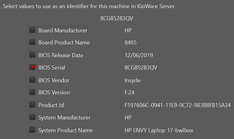
- Board Manufacturer - Manufacturer of the computer's motherboard.
- Board Product Name - Product name of motherboard used in the computer.
- BIOS Release Date - Your computer's Basic Input/Output System (BIOS) release date.
- BIOS Serial - Your computer's BIOS serial number.
- BIOS Vendor - Your computer's BIOS vendor.
- BIOS Version - Your computer's BIOS version.
- Product Id - Device ID number.
- System Manufacturer - Manufacturer of the computer.
- System Product Name - Make and model of the computer.
System Battery
The screen looks like this when the “Device Type” dropdown is set to “System Battery”.
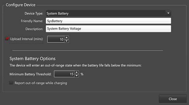
- Minimum Battery Threshold - Minimum charge (in percentage) the battery can have before the battery status changes. Once the battery charge falls below this value, it will enter an out-of-range state and can no longer be shown.
- Report out-of-range while charging - If checked, and the battery has reached its out-of-range state (see above), then an out-of-range state will be indicated while the battery is charging.
Geolocation
The screen looks like this when the “Device Type” dropdown is set to “Geolocation”. Geolocation data can now be obtained using Windows Geolocation Services (see Browser Tab, Geolocation Mode, Using Windows Geolocation and Advanced Tab, Advanced Settings Tab, Static Location for details on enabling Windows Geolocation Services and using static location input).

Related Terms and Questions
If the answers to your questions are not in this table, visit the KioWare website for frequently asked questions (FAQs).
| What is DLP-TH1? | DLP Design, Inc. produces the DLP-TH1 digital USB sensor. When plugged into a USB port of your kiosk or computer, this sensor can remotely monitor how your devices are running and help you to troubleshoot any problems before they arise, reducing damage and downtime to your equipment. The DLP-TH1 will alert you if a device's temperature becomes too low or too high (i.e., if it goes outside of the minimum or maximum temperatures you set on the Configure Device window). It also will tell you if a device's humidity becomes too low or too high (i.e., if it goes outside of the minimum or maximum humidity you set on the Configure Device window). |
| What is OPOS device setup? | Let's first define OPOS, beginning with POS. Point of Sale (POS) is the time when a customer makes payment in exchange for goods or services. Object Linking and Embedding (OLE) is a technology created by Microsoft that allows parts of documents (text files, images, etc.) to be incorporated into a master document (embedding). This master document can also link to parts of other documents (linking). The purpose of OLE is to both manage these compound documents and send/receive data between various software applications. OLE for Retail POS (or OPOS) combines a point of sale with object linking and embedding by setting up the rules for using retail devices (e.g., receipt printer) with software for making sales. In this way, part of each sales document (receipt) can be embedded or linked to in another master document that a marketing department might use to analyze trends in purchasing. |
| What are ChipDNA devices? | When a device is used for credit card transactions (purchases, credits, etc.), the device, its software, and its protocol (rules it follows when sending or receiving data) must all be “certified”, to check that they all can be used with each other. This certification process can be very slow and very costly for each transaction. ChipDNA is a web-based platform that acts as a “middle man” by completing this certification process faster and more easily. When devices are used that ChipDNA supports, each transaction goes through ChipDNA for certification, and if certified, the transaction is completed. For a list of supported ChipDNA devices, use the Device Search on the KioWare website. |
| What are ChipDNA support files? | Special ChipDNA software is available to run with your ChipDNA device (see above). ChipDNA support files are files that you download and run on your kiosk or computer (that is running KioWare) to install this special software. Select the “Add Input Device” button and on the Configure Device window, select “ChipDNA Device” in the “Device Type” dropdown. A button appears to download ChipDNA support files if they are not already installed. Select this button and you will download a setup (.exe) file. Run this file to install the software in the ChipDNAServer folder under your installation directory (see Installation, Installation Instructions, Default Install Directories). This software can be used to set up your ChipDNA device for use with your kiosk or computer. |
| I set up KioWare to run with Code CR-1000, but the device is not working. | Be sure the device is in USB Virtual COM One Way Mode (see “USB Settings, USB Virtual COM One Way Mode” in the Code Corporation CR-1000 Configuration Guide for more details on this mode). |
| When using the Code CR-1000, does the Carriage Return Suffix have to be enabled? | Though it had to be enabled with earlier versions of KioWare, it no longer has to be enabled with version 8.2 and higher. (See “Data Formatting (Prefix/Suffix) Settings, Erase Suffix Data - Default” in the Code Corporation CR-1000 Configuration Guide for more details.) |
| What is a Numato General Purpose IO Board? | KioWare supports the General Purpose Input/Output (GPIO) Board manufactured by Numato Systems. This board is an integrated circuit board containing metal pins that can be used to form electrical connections. By default, the pins are not set up to behave in any certain way; they are controlled by the user via the main Pin Details tab. If the board is connected to a kiosk or computer that is running KioWare, this tab can be used to specify pin settings, including if pins will serve as input or output pins (“OUTPUT” toggle) and if output pins will be low voltage or high voltage (“LOW” toggle). Use the “Add GPIO Auto Action” button on the Automatic Actions tab to add a new automatic action entry. Then select the pencil icon to set the pin conditions that must be met to trigger the automatic action (on the Pin Details tab) and specify the automatic action that will occur (on the Action tab). |
| What is an OTI reader? | It is a device manufactured by OTI that accepts payment using the major credit cards (e.g., American Express, MasterCard, Visa, and a few others - referred to as an EMV payment solution) but does not accept cash. OTI readers are specifically made to work with kiosks. Special software is available from OTI to use with the readers (see below). Once the software is loaded on the kiosk or computer (that is running KioWare) and an OTI reader is connected, select the “Add Input Device” button on this tab. Next, in the “Device Type” dropdown on the Configure Device window, select “OTI Reader” to tell KioWare to use the OTI reader. |
| What are OtiKiosk support files? | Let's first begin with OtiKiosk. OtiKiosk is the name of a kiosk payment acceptance and management solution available from OTI. This solution includes hardware (an OTI reader that accepts payment using the major credit cards; see above) and special OTI software to run with the reader. OTI support files are files that you download and run on your kiosk or computer (that is running KioWare) to install the special software for use with your OTI reader. After selecting “OTI Reader” on the Configure Device window (see above), a button appears to download these files if they are not already installed. Select this button and you will download a setup (.exe) file. Run this file to install the software in an otiKiosk folder under your root directory (typically the C: drive). This software can be used to set up your OTI reader for running payment transactions through your kiosk or computer. |
| What is HTML form fill? | This feature tells KioWare to use any major credit card to auto-fill a form on your web page [used only with magnetic stripe reader (MSR) input devices]. Use the Configure Device window to set this up in KioWare. First, select “HTML Form Fill” in the “Send Data Via” dropdown. Then, use the “Add Form Fill Entry” button and the “HTML Form Fill Element” dropdown to tell KioWare what fields (e.g., text entry boxes or dropdown boxes) you want to auto-fill. If you want to auto-fill any field based on its ID (name) that is used in the web page, then set the “By ID/Select” toggle to “By ID”, and enter the field ID in the box to the left. To auto-fill any field using CSS selectors (see below), set the “By ID/Select” toggle to “Select”, and enter the CSS selector in the box to the left. |
| What are Cascading Style Sheet selectors? | HTML pages often have a cascading style sheet (CSS) that sets up the styles (font type and size, spacing, font and background colors, styles for headings, lists, and tables, etc.). CSS selectors are tidbits of code that are used to “select” (find) certain elements of an HTML page using their ID (name), element type, or other things assigned to them that help identify them. As an example, you can use CSS selectors to find every third dropdown field or every option in a dropdown that begins with “Date”. Within KioWare, CSS selectors can be used to find certain HTML elements of a form on your web page and auto-fill them (see above). Enter the CSS selectors on the Configure Device window and set the “By ID/Select” toggle to “Select”. |
| What is an input device access list? | It is a list that tells KioWare which input devices it can or cannot link to, based on web pages that are opened in the KioWare browser. When pages are blocked for a certain input device, the device cannot link to KioWare when these blocked pages are open. When pages are allowed, a device can receive data from those pages when they are open. Using the “Input Device ACL” button on the Configure Device window, you can block or allow pages in a domain (root of a website, such as kioware.com). Specific pages within a domain (e.g., kioware.com/support.aspx) can also be blocked or allowed. Remember that when adding domains, you should not include protocols at the beginning (e.g., “http://” and “https://”). (See Security Tab, Related Terms and Questions for tips on allowing and blocking domains and pages.) |
| What is Fujitsu F53? | It is a dispenser made by Fujitsu that can give out cash (bills) as well as multi-media items (e.g., tickets, stamps, phone cards, and vouchers) during purchases and other transactions. The F53 connects to your kiosk or computer via a USB port or RS232 interface (serial port) and runs with KioWare. Special software (see below) is then installed on the kiosk or computer to set up the F53 to run in the desired way, and to tell KioWare how to operate the F53 during transactions. |
| What is ARCA Envoy? | Envoy is the name of an application programming interface (API) made by ARCA. An API allows computer programmers to write software applications that have a similar “look and feel” as a certain operating environment (e.g., MS Windows or Google), and also follow the same rules and guidelines as that environment. APIs generally provide programmers with standard commands, functions, and rules for use in software, hardware, and/or networks. They also can include “templates” for setting up screens/windows, scrollbars, buttons, etc. In short, a good API provides the basics so that programmers do not have to start from scratch when creating programs to run and “blend” in a certain environment. (Google has an API that allows Google Maps to be used with KioWare; see Browser Tab, Related Terms and Questions for more details.) Within a kiosk, there may be different devices (one to accept cash payments, one to give out change, one to scan a credit card, one to print, etc.). Each one might run in a different operating environment. Software for such a kiosk typically would have to be compatible with all of these operating environments, making it somewhat challenging to create. ARCA's Envoy is intended to be an all-in-one API that is compatible with multiple devices and operating environments as well as multiple programming languages and currencies, making it very easy to create kiosk software. With KioWare, Envoy can be used for compatibility with the Fujitsu F53 bill dispenser (see above) and its operating environment. Select the “Add Output Device” button on this tab, and then select “Fujitsu F53 (via ARCA Envoy)” in the “Device Type” dropdown to tell KioWare to run with the F53. |
| What are Envoy support files? | They are special files that you download and run on your kiosk or computer (that is running KioWare) to install everything needed to use the Envoy API (see above). Select the “Add Output Device” button and on the Configure Device window, select “Fujitsu F53 (via ARCA Envoy)” in the “Device Type” dropdown. A button appears to download Envoy support files if they are not already installed. Select this button to download them. The files allow use of the Envoy API for operating the Fujitsu 53 (see above) with your kiosk or computer. |
| What is a PJL Printer? | Let's start with printer language. When printing, every printed page has what is called a page description language (PDL). Using a special computer language, a PDL includes commands that describe what is printed on the page/how it should appear and also tell the printer how to print it that way. Some common PDLs are PDF, XPS (saving files as XPS documents is a feature in Vista and later versions of MS Windows), and postscript (used with printing presses for large-scale printing of books and magazines). Hewlett-Packard (HP) created its own PDL that it calls Printer Command Language (PCL). A little later, HP developed Printer Job Language (PJL) as an extension of PCL. With PJL, there are job-level controls for switching the printer language, separating jobs, setting printer default settings, viewing the current printer status, and other controls. Not every printer uses PJL, but many do. In KioWare, you can monitor a PJL-supporting printer. Select the “Add Monitored Device” button and then select “PJL Printer” from the “Device Type” dropdown. This tells KioWare to allow monitoring of PJL printers that are connected to your kiosk or computer. To tell KioWare which specific printer(s) to monitor for PJL, open the Config Tool menu, select the “Printer Language Monitor” option, and check the box for each printer that you want to monitor (see Config Tool Menu, Printer Language Monitor). |
| What is Watchport T/H? | Digi International, Inc. produces Watchport series of USB sensors. When plugged into a USB port of your kiosk or computer, these sensors can remotely monitor how your devices are running and help you to troubleshoot any problems before they arise, reducing damage and downtime to your equipment. Watchport/T is a temperature sensor that will alert you if a device's temperature becomes too low or too high (i.e., if it goes outside of the minimum or maximum temperatures you set on the Configure Device window). Watchport/H is a humidity sensor that will tell you if a device's humidity becomes too low or too high (i.e., if it goes outside of the minimum or maximum humidity you set on the Configure Device window). |